Hardware Description
Schematics
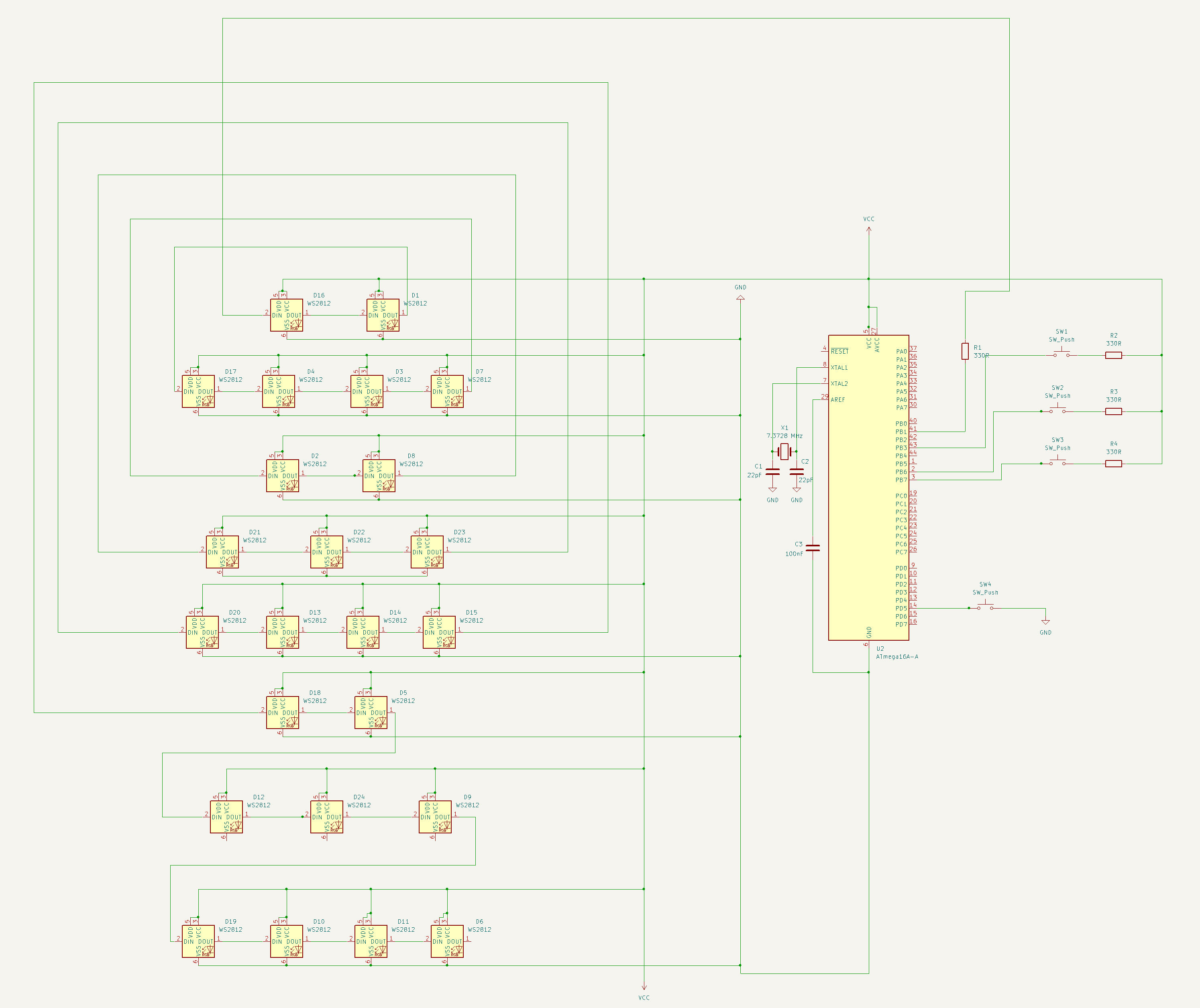
The schematic was created in KiCad. It includes:
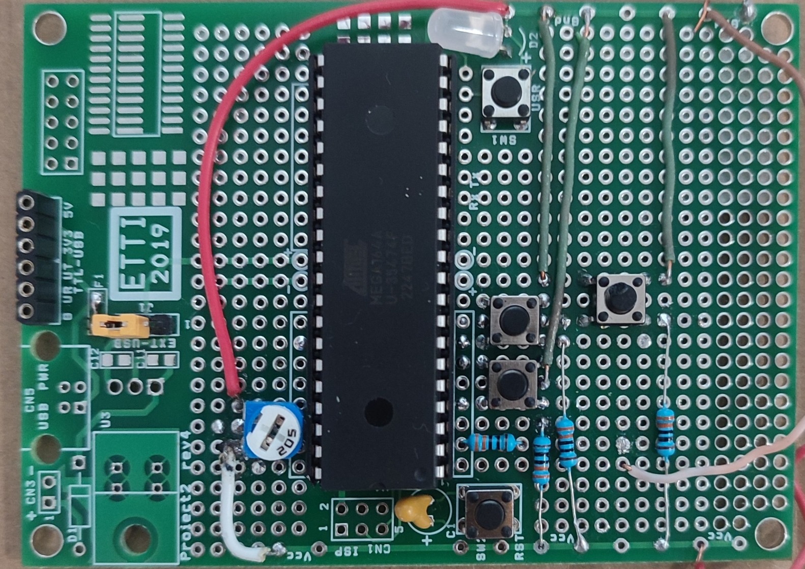
- ATmega164A microcontroller: Acts as the main controller of the binary clock system.
- WS2812 LEDs: A series of 24 individually addressable LEDs arranged in logical time display groups. These are controlled via a single data line connected to pin PB1 (PORTB.1).
- Input buttons: Four push-buttons connected to PB3, PB6, PB7, and PD5 are used to toggle modes and increment hours, minutes, and seconds during setup.
- Resistors: Several 330Ω resistors are placed in series with the buttons as current limiting or pull-down/up resistors.
- X1 – 16 MHz Crystal Oscillator: Provides the clock signal for the microcontroller's system timing. Ensures accurate timing for WS2812 data transmission.
- C1 and C2 – 22pF Capacitors: Connected to the crystal oscillator (X1), they stabilize the oscillator circuit and ensure proper startup and frequency stability of the crystal.
- C3 – 100nF Decoupling Capacitor: Placed close to the ATmega164A's VCC and GND pins to filter out voltage spikes and provide a stable power supply for the microcontroller.
Bill of Materials
| Cantitate | Ref | Valoare | Capsulă | Obs | Furnizor, cod produs | Preț unitar (lei) |
|---|---|---|---|---|---|---|
| 24 | D1-D24 | LED BAND | THT | UPB | ||
| 4 | R1,R2,R3,R4 | 330Ohm | THT | ardushop.ro, CJADNL_CR1/4W-330R-5pc-ST26 | 0.27 RON | |
| 2 | C1,C2 | 22pF | SMD | UPB | ||
| 1 | U1 | ATMega16A | DIP40 | UPB | ||
| 1 | C3 | 100pF | THT | UPB | ||
| 1 | X1 | Crystal | THT | UPB |
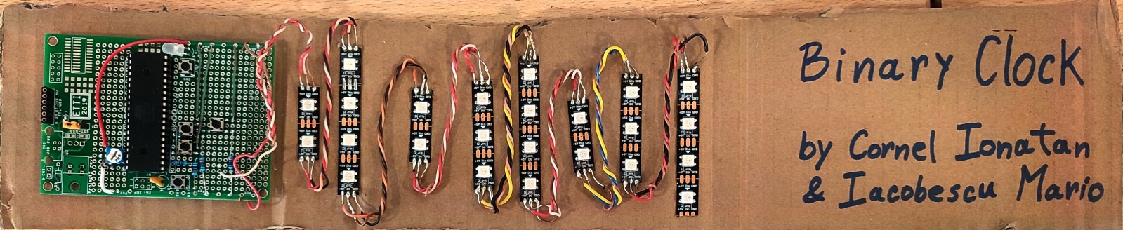
Additional Hardware Features
The project uses WS2812 LED strips for visual time display, controlled via a single data line on PB1. Four push-buttons connected to PB3, PB6, PB7, and PD5 allow user interaction for setup and time adjustment:
- PB7: Toggle between normal and setup mode.
- PB3: Increment hour in setup mode.
- PB6: Increment minute in setup mode.
- PD5: Increment second in setup mode.